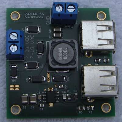
I have a Kickstarter campaign running for this little board, the PWRLNK-55, which converts the kind of voltages we see on solar panels, often around 21 Volts, down to the very useful 5 Volts used by USB and many electronic devices. The post a few weeks ago about hand soldered surface mount was on one of these prototypes.
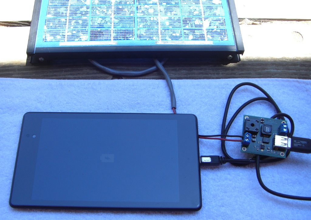
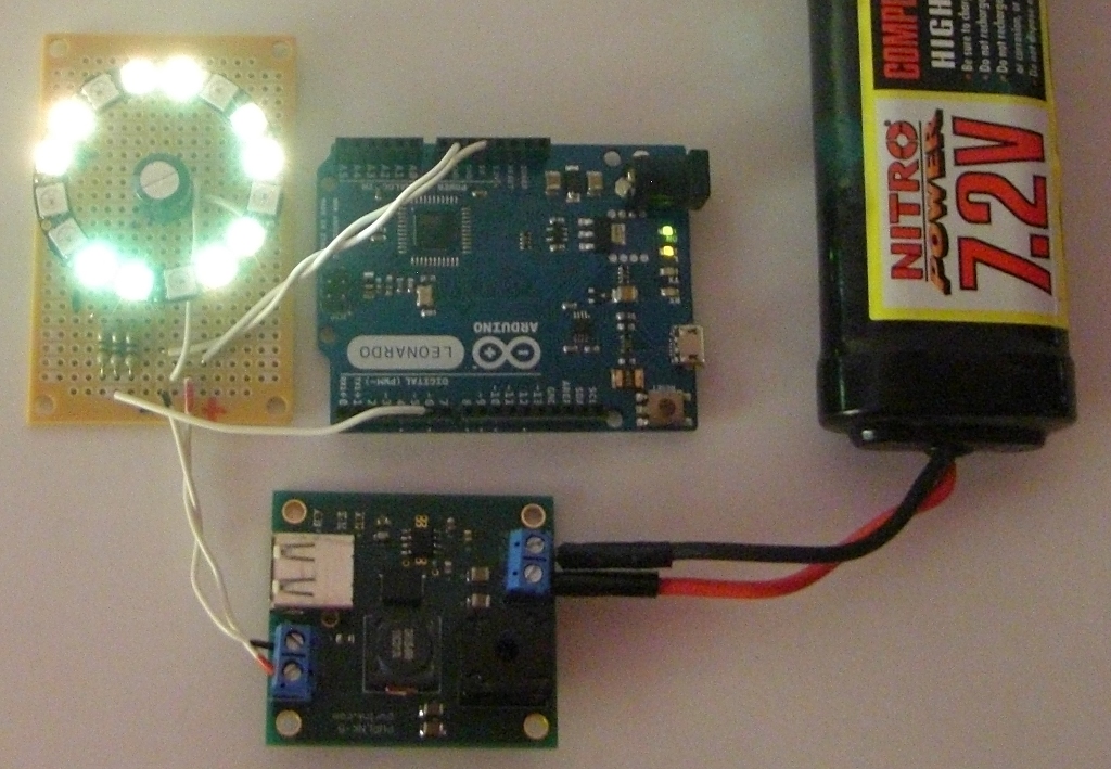
Here’s a small solar panel powering an Arduino board and some servo motors. The panel output is too high for the Arduino to accept directly. The PWRLNK-55 efficiently converts the panel voltage down to 5 Volts for the USB port.
Switching power supplies like this convert high voltage low current into lower voltage higher current, preserving most of the overall power.
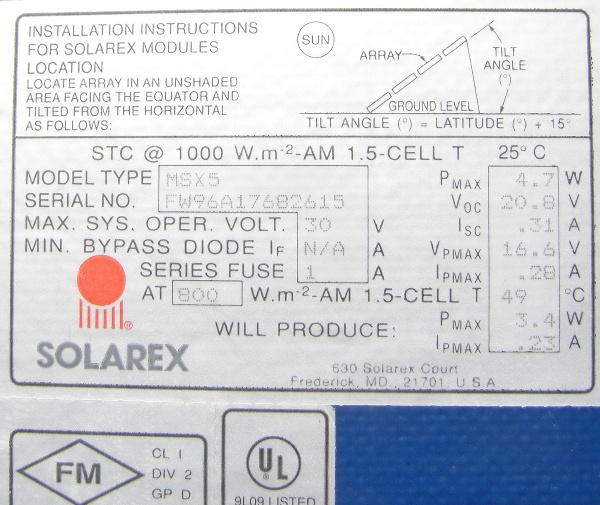
The maximum power point of this panel is 16.6 Volts at 0.28 Amps for 4.7 Watts. The PWRLNK-55 is about 90% efficient, so 4.2 Watts / 5 Volts = 0.85 Amps. That’s much better for small devices than using a linear regulator with a big heat sink, and getting only the 0.28 Amps with a lot of waste heat.
The USB outputs support the 1.5 Amp Direct Charging Port standard for charging phones, tablets and other modern devices.
Lots of electronics including Do-It-Yourself designs don’t use USB, so there are also screw terminal outputs for simple wire connections.
Please visit the Kickstarter page:
https://www.kickstarter.com/projects/205568268/pwrlnk-the-versatile-power-converter


Pete, the link above doesn’t seem to work…
The campaign was cancelled at the end of August, since it was going to fail for non-technical reasons. The marketing/promotion part was much harder than expected and the price was too high. I will be re-launching it again soon with the same PWRLNK name. Google shows lots of links for it.
Hello
i dislike very much for your campaign but i would like to ask you an explanation.
I have read that for the ” V1 version ” you have used the TI LM2676-5 to obtain (from 12v to 30 volts input) 5V output up to 3 Amps (wirtten on: pwrlnk.com/?q=node/4).
But,looking on Github,i have watched that(in the open hardware schematic that you have published) you have used the LM2676SX-5.0/NOPBCT-ND
Could you say me if the data you have published on Github (including also the LM2676SX-5.0/NOPBCT-ND)are the exact data and the exact components (induttance,diode,capacitors) that you have used to obtain the functionally V1 version that you have constructed ?
I’ m sorry ,i wanted to say displeasure and not dislike for your campaign (if you can correct the word error).
Carlo,
The longer -ND number is the Digikey part number, with voltage and package type.
If you get parts from another distributor, search for the root name LM2676 and choose the right variant.
Yes, the design materials on github are a snapshot of the files I used to build these boards. The parts.txt file has the exact parts.
Pete
Thank you very much Pete.
I would like to ask you if the V1 version (5V output up to 3 Amps) has been tested by you and it works perfectly (without any problem).
I have read that the V2 version (5V output up to 5 Amps) has been tested as you wrote on Kickstarter but i have not read anything test about the V1 version.
Might you say me this thing about the V1 version?
Carlo,
Yes, the version V1 works correctly as documented. The pwrlnk.com page talks about the efficiency measurements I made with V1.
The later 5 Amp versions are a bit more complicated, and I would not have done those if the first one had not worked well.
Pete
Thank you very much Pete.
I have read about the efficiency measurements that you have made with the V1 version but i have had a my doubt because,on the version you have published on Kickstarter,there is written explicitly that you have tested and works perfectly.
I had thought that also this version operates perfectly but,to clarify a my doubt,i have prefered to ask you this other thing.
Thanks again.